
Measurement Capabilities and Traceability
LF, HF Impedance and DC Metrology sub-division is part of the electrical and electronics metrology division, which provides calibration services for a large number of electrical parameters, standards and instruments. The laboratory is responsible for maintaining national and reference standards of impedance parameters upto radio frequencies, precise ac voltage ratio, dc voltage, dc current, and dc resistance and dc high voltage up to 100 kV.
The metrological traceability to SI units are derived from Josephson Voltage Standard (JVS) and Quantum Hall Resistance (QHR) standard, which are being maintained at CSIR-NPL. The primary standard of current (ampere) is derived from JVS and QHR through the Ohm’s law of electrical conductivity. A brief description of the latest revision of the SI units; this assumes importance particularly as the ampere is being defined using the fundamental constant of electron charge (e).
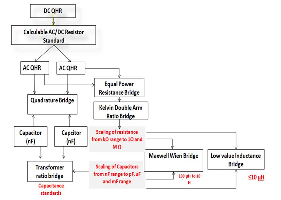
Traceability Chart for Impedance MetrologyThe fused-silica capacitor standards of 10 pF and 100 pF are driving the traceability of impedance standards and the scaling of capacitance was performed through the four-terminal capacitance bridge and capacitance bridge from General Radio. The quadrature bridge is used to assign the resistance standard in terms of capacitance standards and Kelvin double-arm bridge used for scaling the resistance from 1 Ω to 1 MΩ. Thereafter, the inductor standards are defined in terms of resistance and capacitance standards through Maxwell-Wein Bridge. CSIR-NPL utilizes the high value capacitance bridge for 10 μF to 10 mF values while low value inductance-bridge is used to measure inductance values equal to below 10 μH.
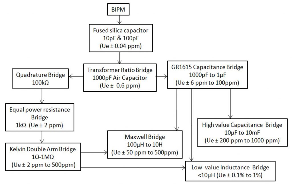
Traceability chart for the impedance metrology laboratory at CSIR-NPL
The mandate of the LF, HF Impedance Metrology is to maintain and disseminate the unit’s related capacitance, inductance, AC resistance, Inductive-voltage-divider (IVD), ratio transformers, LCR meter, impedance analyzer and capacitance bridge. All these quantities are linked to the respective primary / National standards through an unbroken chain of traceability. With a total number of 8 CMCs (listed on the BIPM portal), this section is internationally competent in almost all quantities related to impedance parameters.
Measurement Capabilities- Fused Silica capacitor (10 pF, 100 pF) @ 1 kHz
- Air Capacitor (10 pF, 100 pF & 1000 pF) @ 1 kHz
- Mica Capacitor (0.1 µF, 0.01 µF, 0.001 µF & 1 µF) @ 1 kHz
- AC Resistance (1 Ω to 1 MΩ) @ 1 kHz
- AC Voltage Ratio (using Inductive Voltage Divider) at 1 kHz
- Standard Inductors: 100 µH to 10 H @ 1 kHz
- Low value Inductor from 0.1 µH to 10 µH @ 1 kHz
- Precision LCR meter and Capacitance Bridge
Traceability of impedance parameters are maintained through coaxial bridges which are at par with international standards.
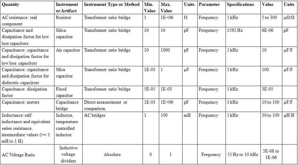
Table 3 Measurement Capabilities of LF, HF Impedance Metrology laboratory at CSIR-NPL
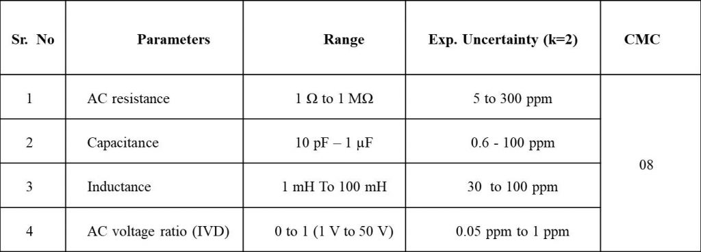
Table 4 Calibration and measurement capabilities registered at BIPM (KCDB database)
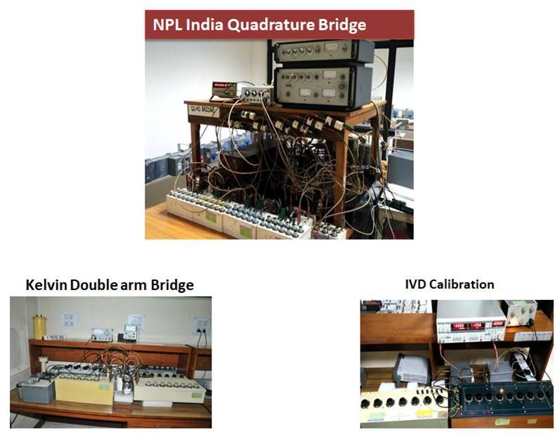
Measurement Facility
- Quadrature Bridge
- Kelvin double arm AC resistance Bridge
- Maxwell-Wein Bridge
- Absolute calibration of IVD
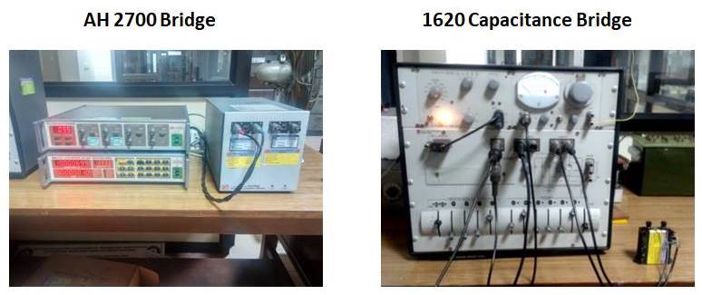
- 1. Ultra precision capacitance bridge
- Model AH2700
- Frequency Range: 20 Hz to 20 kHz
- Make: Andeen Hagerling
- 2. Capacitance bridge
- Model 1615 (1620 capacitance assembly)
- Frequency Range: 50 Hz to 10 kHz
- Make: General Radio
- 3. Capacitance bridge
- Model 1616 (1621 capacitance assembly)
- Frequency Range: 50 Hz to 10 kHz
- Make: General Radio
LCR Meters
- 1. LCR Meter
- Model E4980A
- Frequency Range: 20 Hz to 2 MHz
- Make: Agilent’s Technologies
- 2. High frequency LCR Meter
- Model 4285A
- Frequency Range: 75 kHz – 30 MHz
- Make: Agilent’s Technologies
- 3. RF Impedance / Material Analyzer
- Model E4991A
- Frequency Range: 1 MHz – 3 GHz
- Make: Agilent’s Technologies
AC Impedance Standards upto Radio Frequency
Coaxial Airlines
Low value capacitance standards (2 pF -20 pF) upto 100 MHz, Coaxial Airline GR 900, LZ Series Four-terminal air pair (4TP) capacitance Standards (1 pF – 1000 pF) upto 30 MHz, Agilent’s Model 16380A
Four-terminal pair capacitance standards (10 nF – 1 μF) upto 1 MHz, IET Labs, SCA Series
Four-terminal pair resistance standards upto 1 MHz, Agilent’s Model 16074A
A set of seven GR900 Type LZ series coaxial air-liness has been realized as reference standard of low value capacitance. The dimensions of coaxial air-lines; the outer diameter of inner conductor (a), inner diameter of outer conductor (b) and geometrical length of air-line (l_g) have been measured precisely and are traceable to the primary standard of length being maintained at CSIR-NPL. The transfer or reference standards of capacitance include coaxial capacitance standards and four-terminal-pair (4TP) air capacitance standards. These reference standards are used in turn to calibrate high precision LCR meters and impedance analysers.
Four-Terminal Pair Air Capacitance Standards
Four-terminal-pair air capacitance standards from 1 pF to 1000 pF have been evaluated using electrical equivalent circuit model (EECM) as shown in the figure. The approach used for the evaluation is based on the determination of capacitive and inductive residual components of EECM.
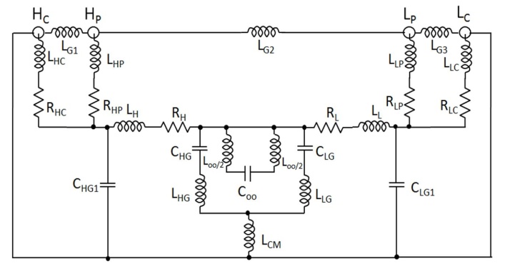
Electrical Equivalent Circuit Model of four-terminal-pair capacitance standards
The frequency characteristics of 4TP capacitance standard involves the use of the relation between S and Z given as
Z4TP= Z0 * [U-S]-1 * [U+S]
Where U is unit matrix [4 X 4] and Z0 is the characteristic impedance, 50 Ω. The procedure used for the evaluation of 4TP capacitance standards is given below:
- Measurement of reference capacitance Co, residual capacitances (CHG & CLG) at 1 kHz using capacitance bridge.
- Estimation of residual inductive components (Loo,LHG & LLG).
- The S-parameters are measured using two-port vector network analyzer. The Nine S-parameters (S12, S22, S32, S24, S31, S34, S41, S42 & S44) are measured from 10 MHz to 500 MHz for each value of 1 pF, 10 pF, 100 pF and 1000 pF and then converted into impedance parameters.
- Determination of series and parallel resonance frequencies of each capacitance standard.
- Determination of residual or parasitic capacitive and inductive of capacitance as per electrical equivalent circuit.
- Computation of 4TP capacitance standards at specified frequencies.
R&D in LF, HF Impedance Metrology
Development of AC –DC Calculable Resistance Standard
Cross calculable capacitance standard based on Thomson-Lampard theorem, was being used as a primary standard of impedance in leading NMI’s till 2000. These capacitance standards were able to provide the uncertainty of the order of 10-7 but are bulky and complex in operation and it has other limitations as well.
CSIR-NPL is working to establish traceability of impedance standards from ac-dc calculable resistance standard that will be traceable to QHR. It is compact, simple to design, and easy to operate and its uncertainty is better than the cross calculable capacitance standards, considering these factors it has become the first choice for a primary standard.
Proposed Traceability Chart of AC impedance through calculable resistance standard
Digitization of Inductive-Voltage-Divider Calibration service using Virtual Instrumentation
Inductive-voltage-dividers (IVDs) are widely used in various ac bridges for precision measurements of electrical parameters. IVDs are often used to generate very accurate voltage ratios, immune to temperature and aging effects. We have used direct comparison method to calibrate the IVDs. In this method, one divider is considered as a device-under-calibration and other as a reference divider.
Manual calibration of IVD is time consuming and many manipulations required to balance the bridge. Digital techniques can reduce the complexity of measurement and reduces the measurement time. An automated calibration procedure of IVD is developed at CSIR-NPL, India based on virtual instrumentation. The bridge balance condition is determined by high-resolution data-acquisition-card (DAQ) instead of analog detectors
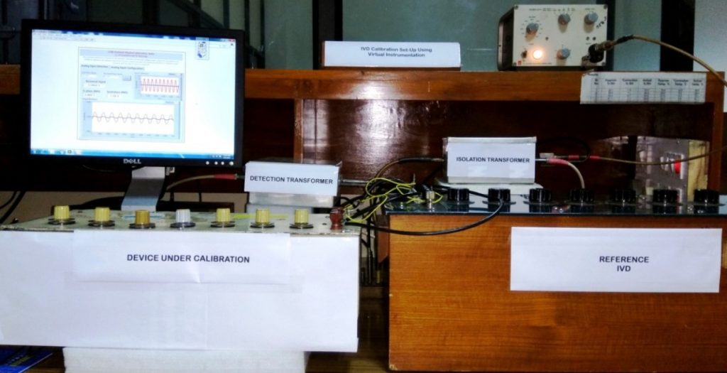
Measurement set-up for the calibration of IVD using virtual instrumentation
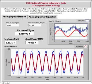
Measurement automation program for the calibration of IVD
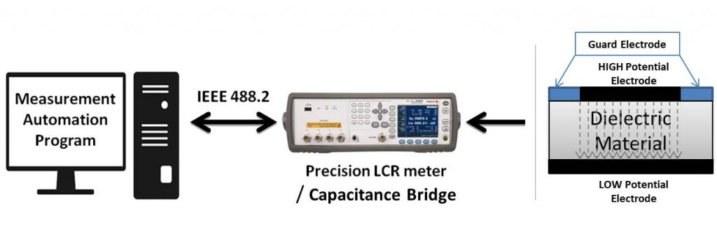
Dielectric Constant Measurement facility for Reference Solid dielectric Material upto 10 MHz
A dielectric constant measurement facility is established for solid-reference-dielectric materials for the frequency range from 1 kHz to 10 MHz. The work complies with ASTM D-150 standards and dielectric test fixture was utilized to establish the facility for dielectric constant measurement.
The dielectric constant measurement is based on the capacitance method as shown in the figure. The contact and non-contact method may be used to compute the dielectric constant of solid materials.
Measurement set-up for dielectric constant measurement
Electrolytic Conductivity Measurement
Electrolytic conductivity is a measure of amount of charge transport of ions. The measurement of electrolytic conductivity is used for the quality control of drinking water in food industry, water treatment monitoring, ion-chromatography in pharmaceutical industry.
Electrolytic conductivity is dependent on the charge, mobility and concentration of ions present in the solution as well as the dielectric constant and viscosity of solvent. Two parallel electrodes cell is popular for the measurement of conductivity using ac method.
A precision LCR meter is used to measure the ac resistance of the test fixture with electrolyte at 10 kHz, 100 kHz and 1 MHz as shown in figure. It is metrological traceable to the national standard of impedance, which is being maintained at CSIR-NPL, through a documented unbroken-chain of calibrations, each contributing to the measurement in uncertainty.
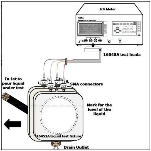
Measurement set-up for the electrolytic conductivity
The electrolytic conductivity is measured at 10 kHz, 100 kHz and 1 MHz with a limited range of electrolytic conductivity. It was observed that measurement of AC resistance performed at 100 kHz is stable and accurate as compared to other frequencies. The computed conductivity of electrolyte solution is close to the reference electrolyte solution and repeatable.
Metrological Services for Industrial Growth
Calibration/ Testing
This division is providing calibration and testing services to a wide range of electrical parameters related to DC voltage, current, resistance, charge, dc high voltage, ac resistance, inductance, capacitance and precise ac voltage ratio. The list of the calibration and testing services provided by CSIR-NPL can be located at website https://www.nplindia.org/index.php/commercial-services/calibration-testing/
The calibration services offered by CSIR-NPL are meeting the requirements laid down in IS/ISO/IEC 17025:2017 regarding technical competency and equipment’s/ instruments. We provide:
- Calibration Services in India
- Traceable to primary/ national standards
- Internationally accepted calibration services under CIPM-MRA
Technological and Technical Consultancy
CSIR-NPL is also providing consultancy services in the following areas:
- Training on quality system as per IS/ISO/IEC 17025:2017
- Training on precision measurement and evaluation of ‘Uncertainty in Measurement’ in the field of electrical and electronics metrology
- Technical consultancy
- Providing support to NABL as technical experts in the accreditation process of the laboratories
Industrial Support
It is our commitment to support Indian industry for their metrological needs. Many industries approach to CSIR-NPL for technical support. Most of the strategic sector including Indian Air Force, ISRO, Naval Dockyard depends on CSIR-NPL for their product evaluations, calibration and measurement requirements. STQC laboratories (ERTL, ETDC), NABL accredited labs and industries depend on CSIR-NPL for their product evaluations, calibration and measurement requirements. As they establish the traceability link with primary / transfer standards of CSIR-NPL, their products and services, become competent and acceptable across the globe under the CIPM-MRA. This in turn helps the Indian industries to enhance their manufacturing/export and other services, thus contributing to the GDP of the Nation.
Beneficiaries : Strategic sector ( ISRO,DRDO, Indian Air force and Defence), Public sector (STQC, ERTL,ETDC, NTPC, NHPC, CPRI, BHEL, BEL, ARAI etc.) and other Organizations including MSMEs, electrical and electronics industry, Automobile industry, manufactures of electrical components and accessories etc.
International Inter-comparisons
LF, HF Impedance and DC Metrology participated in International Inter-comparison for high frequency capacitance standards under APMP (APMP.EM S15). NIM China is the pilot laboratory while NPL, India and NIM Thailand are the participating NMIs. The Inter-comparison of high frequency capacitance conducted for 1 pF to 1000 pF range from 10 kHz to 10 MHz frequency.
Inter-comparison was successfully completed and report of the same was presented in APMP Meeting Nov., 2020. The details of the inter-comparison may be found at the below link:
www.bipm.org/kcdb/comparison?id=579
Scientific and Technical Staff
Dr. V.P.S Awana
Head and Chief Scientist
- Dr. R. P. Aloysius, Sr. Pr. Scientist
- Dr. Sangeeta Sahoo, Sr. Pr. Scientist
- Dr. R. S. Meena, Sr. Pr. Scientist
- Ms. Priyanka Jain, Pr. Scientist
- Dr. Satish, Pr. Scientist
- Dr. Ajeet Kumar, Sr. Scientist
- Ms. Hemavathi Karthik, Scientist
- Ms. Usha Kiran, Sr. Tech. Officer
- Ms. Poonam Sethi Bist, Sr. Tech. Officer
- Ms. Jyotsana Mandal, TO
- Mr. Harish Kumar, TO
- Mr. Sachin Kumar, TA
- Ms. Ashmeet, Tech (I)